In this video we solder on our first ever component, the buzzer. Its got 2 pins, one that has a little plus on top so we need to make sure to get the orientation correct. Once soldered, we are going to trim the buzzer and…done!
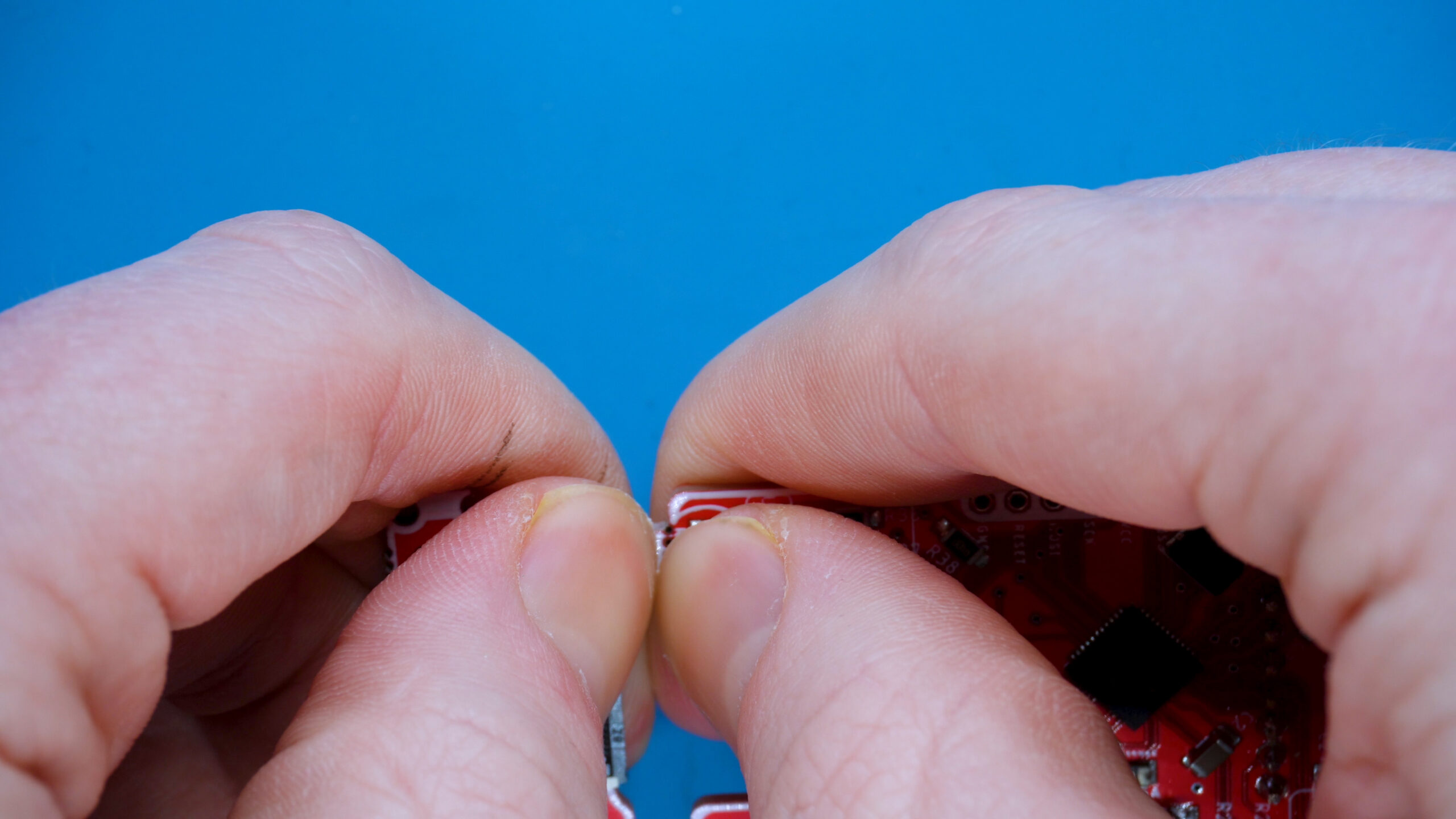
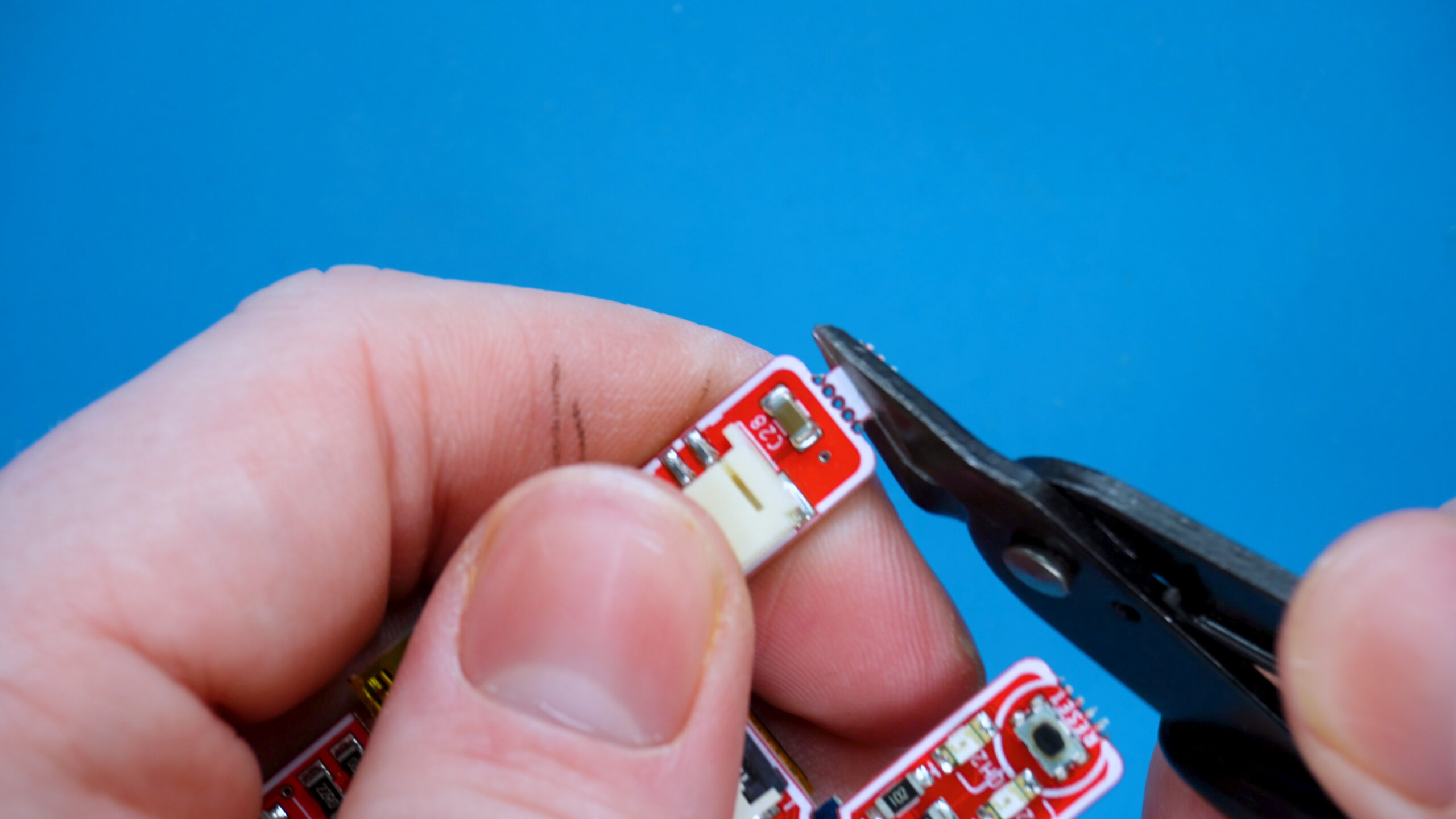
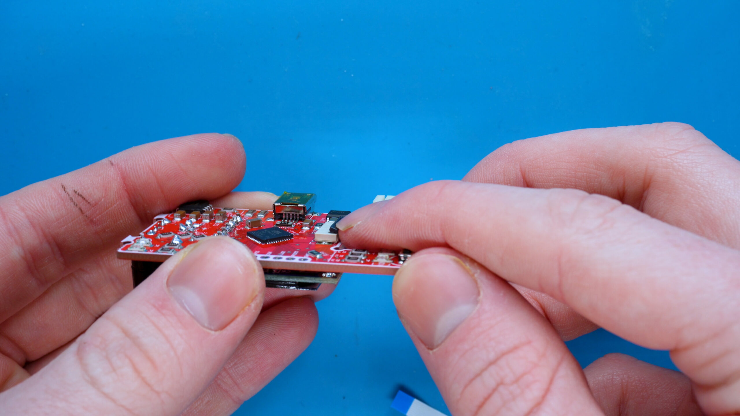
1. Snap off control board
Using your thumbs, apply pressure to break off the control board from the motherboard.
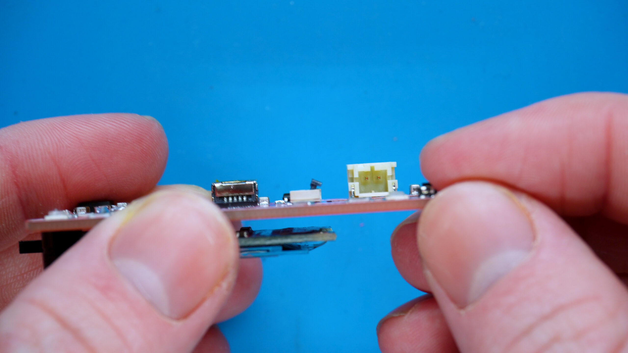
you may find there are 2 white blocks left over. Use your cutters to HOLD the white blocks and TWIST them to SNAP them off. If you are not sure how this works, check out the video above!
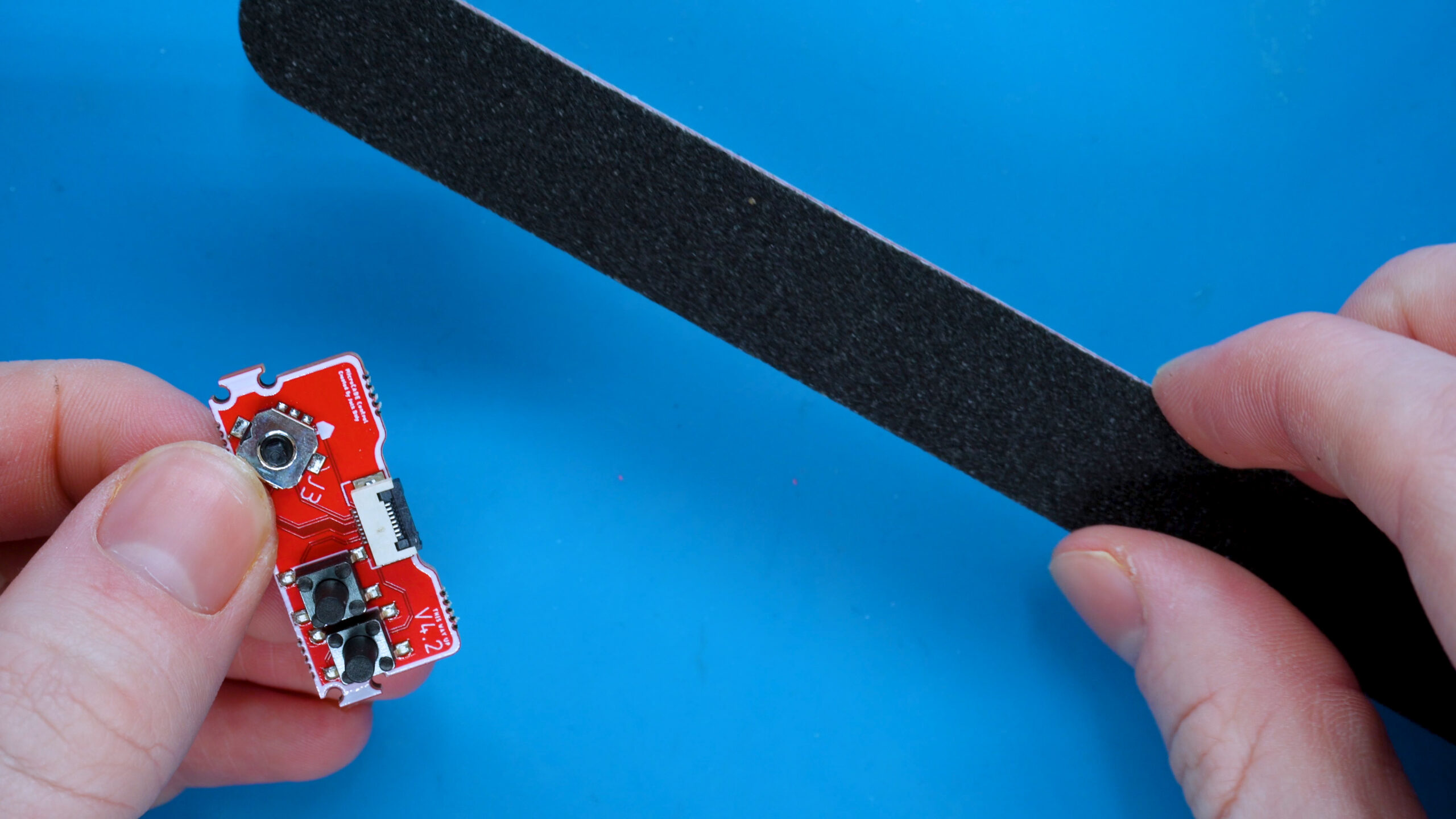
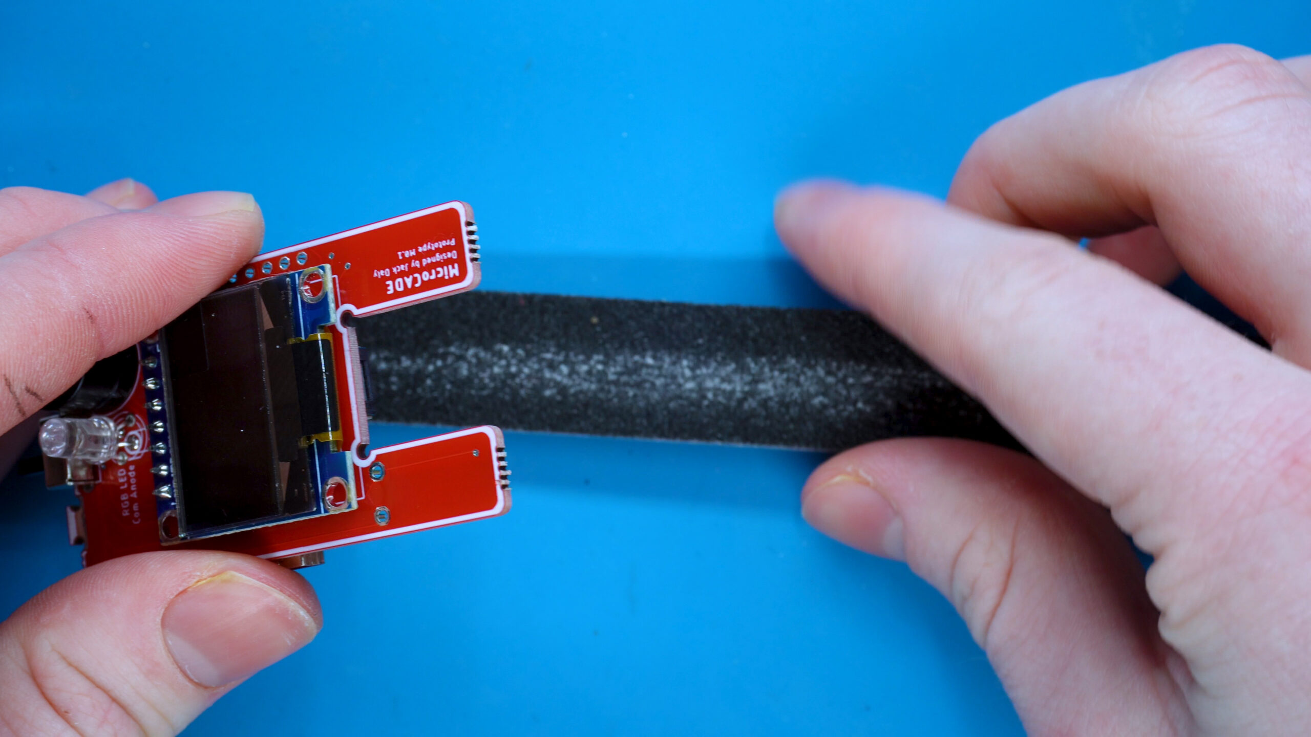
2. File both boards
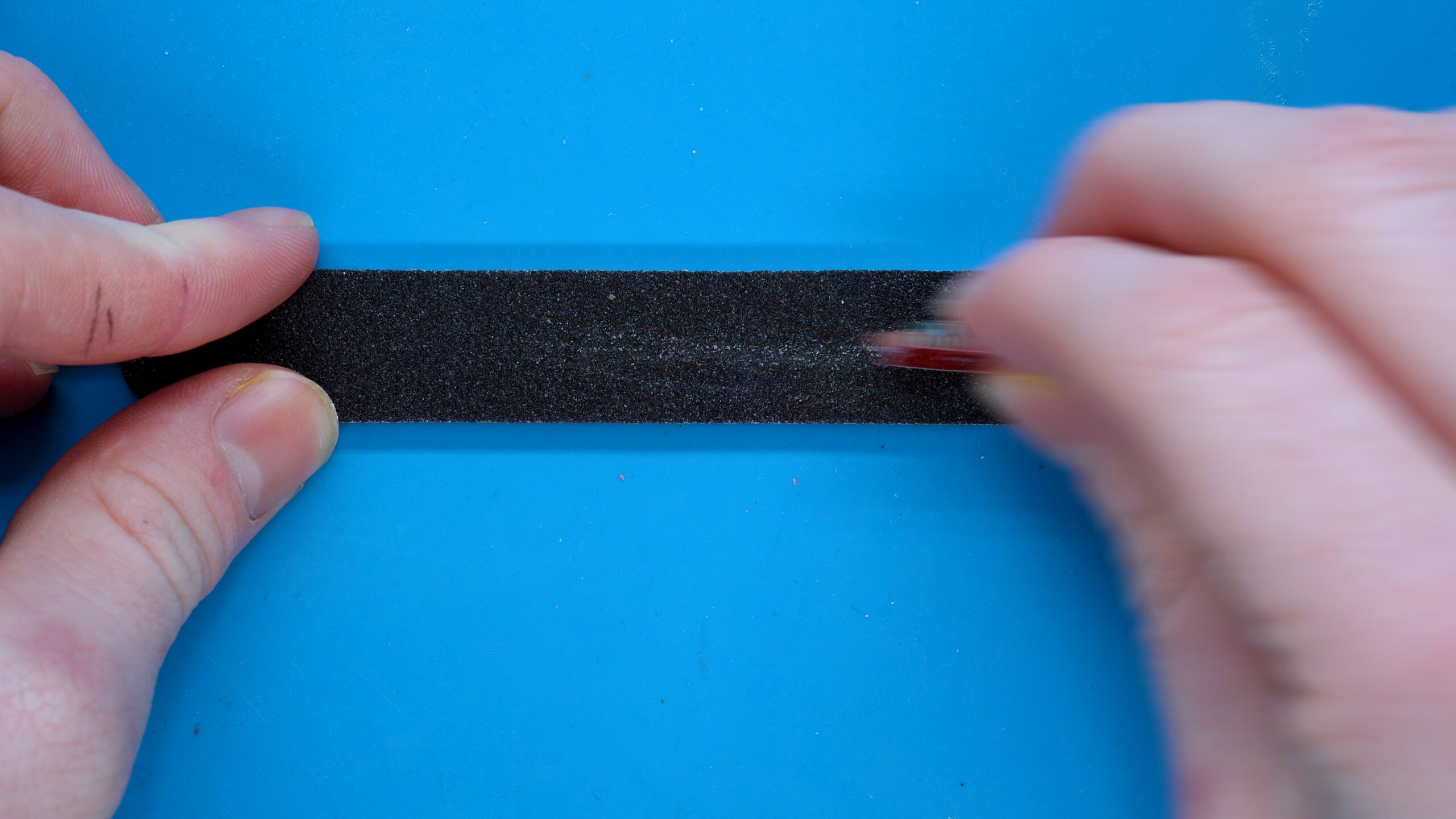
There will be leftover material from where we snapped the tabs off. Use your nail file to file down these edges to make them smooth.
It’s important you file for a few seconds, stop, check with your finger and then decide if you should keep going.
This just stops you from overfilling!
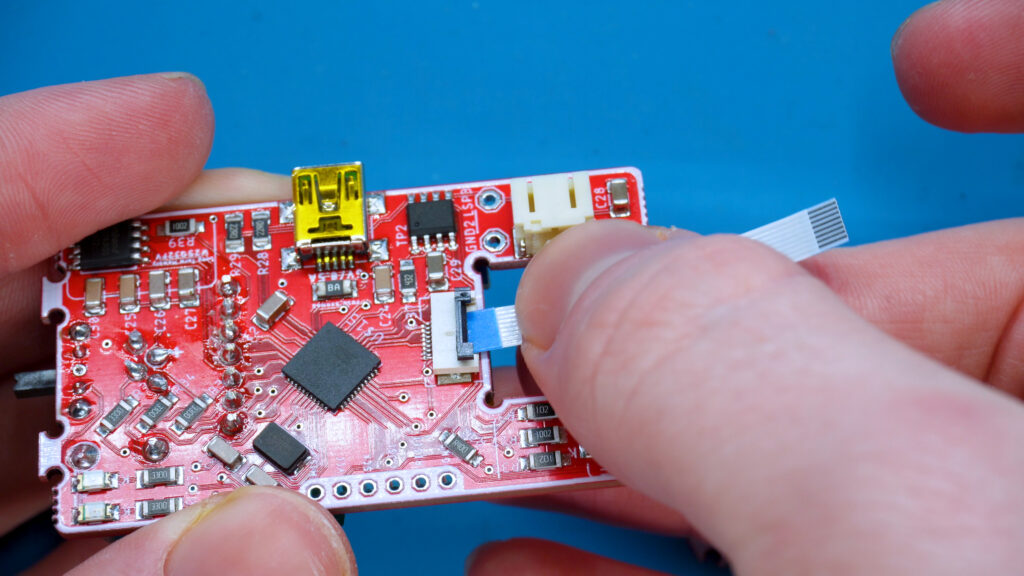
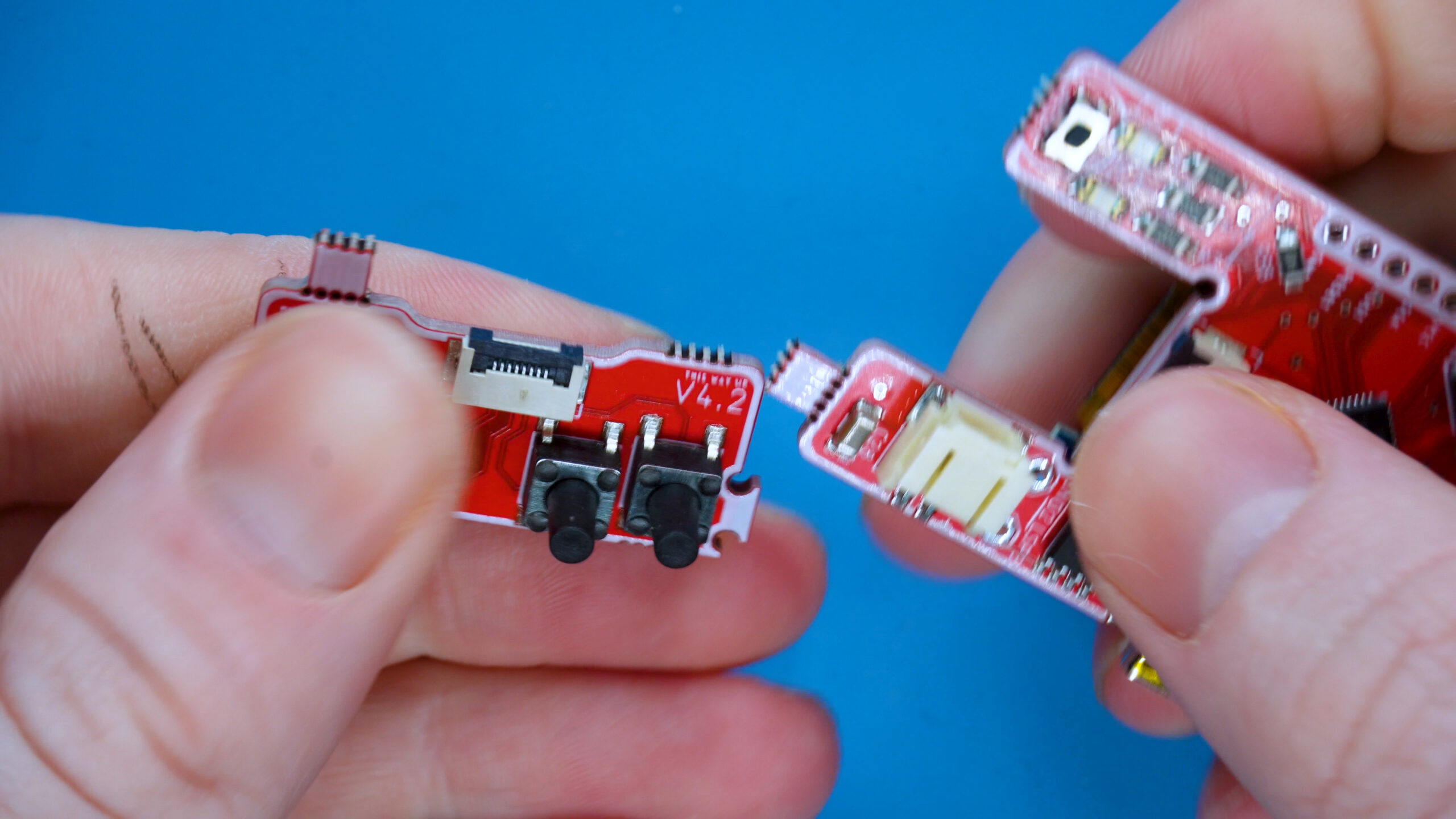
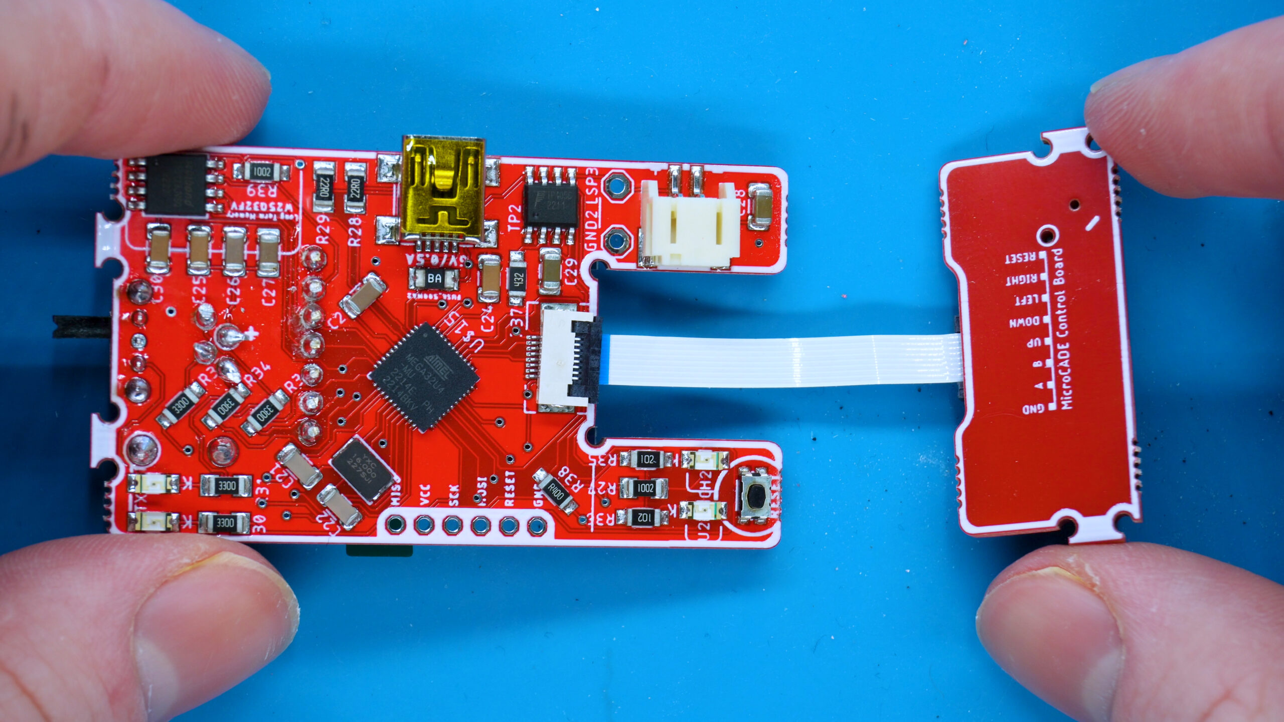
1. Flip the connector door up
Using your finger nail, flick up the connector door so you can push the ribbon cable inside.
2. Push the ribbon cable in
With the blue side facing up, push the ribbon cable in and with your thumb, press the door down. Pull the cable a few times lightly to make sure it is securely in.
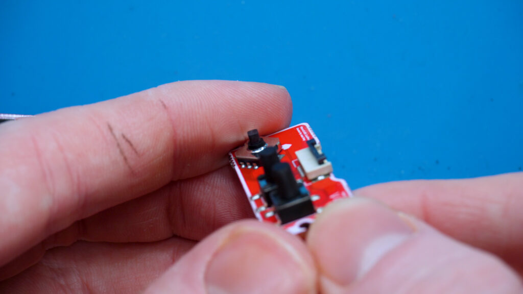
3. Flp the control panel connector up
Using your nail to flip up the connector board’s connectors door up.
4. Flip connector board over and push ribbon cable in
It’s important that the control board is flipped (so the back red side is facing up). Then push the ribbon cable in.
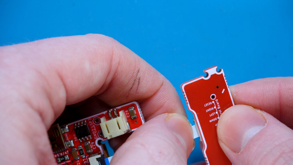
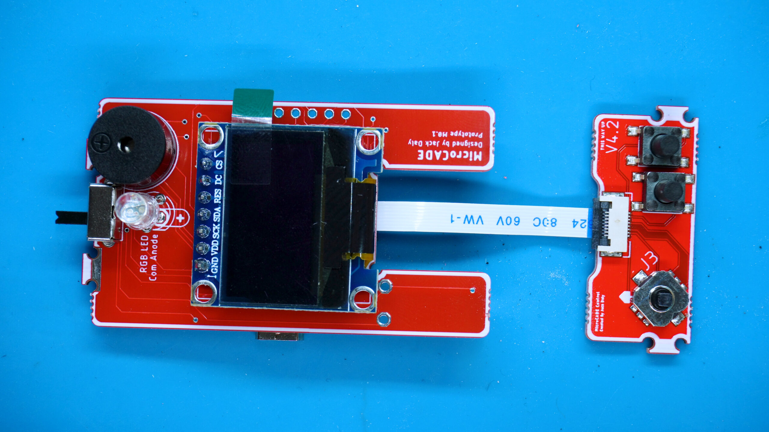
Final connection should look like this
Once the ribbon cable is connected, it should look like this
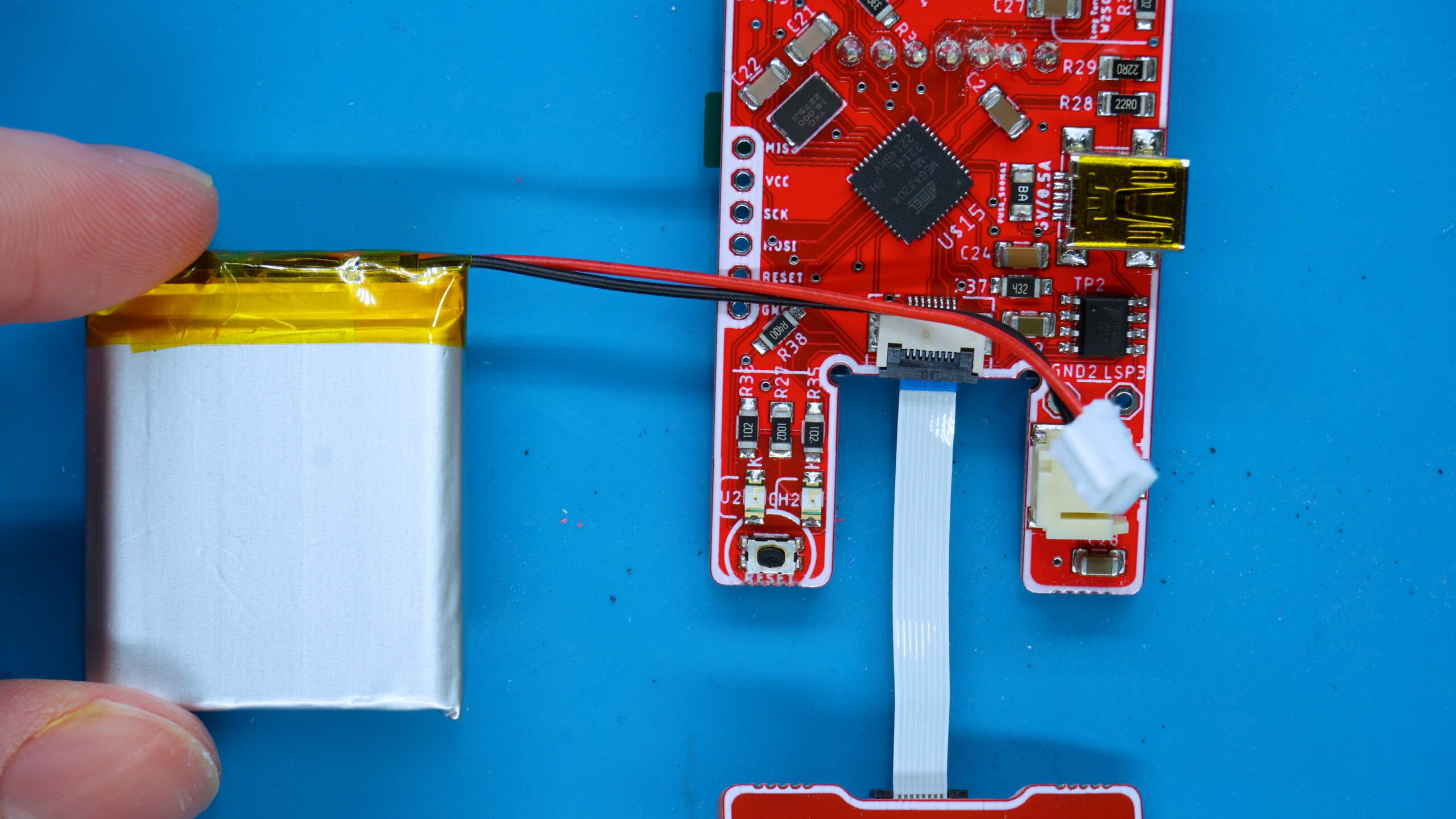
Attach the battery
Connect the battery connection by push the battery connector into the hole. Make sure to align the connector by ensuring the ridge is aligned with the cutout in the hole.